
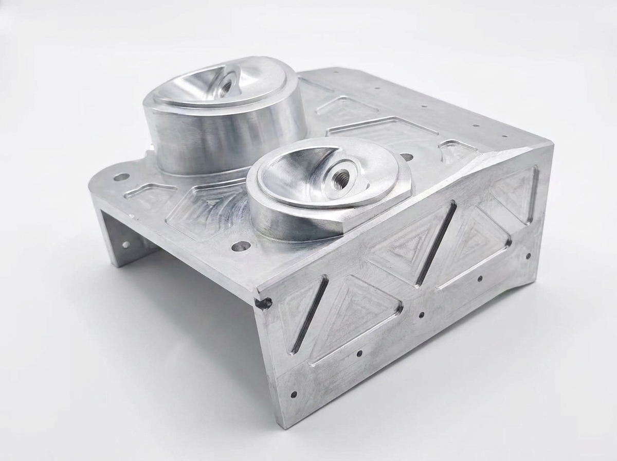
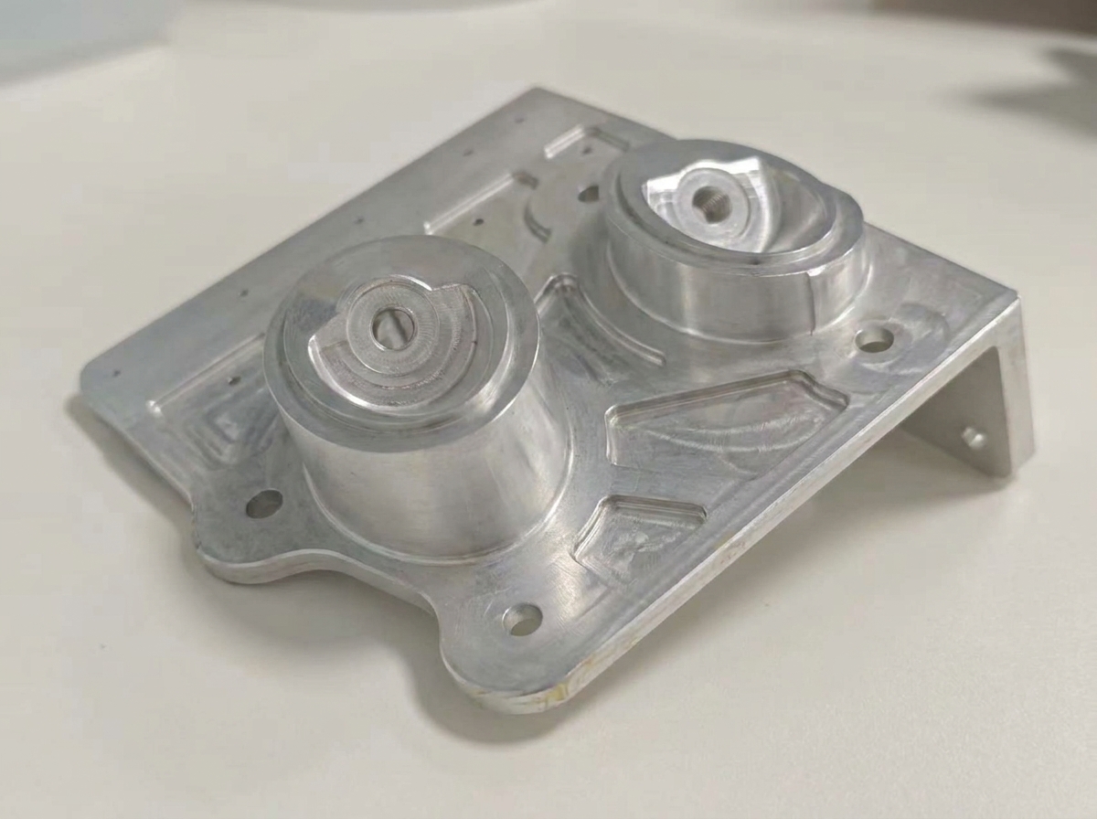
The bracket in the photos is a good snapshot of an automotive program mid-development. Two large machined bosses sit on a flanged aluminum plate, each bored and spot-faced to seat a rubber isolator bushing — the kind of feature you'd expect on an engine, motor, or transmission mount. The body carries a pattern of triangular pockets that mimic the ribbing a future die-cast version would have, and faint blue layout marks are still visible on the surface, left over from a first-article inspection. None of this is a finished production part. It's a CNC-machined bridge unit, built to validate geometry, fit, and function before anyone commits to the far more expensive step of cutting die-cast tooling. This article looks at what that process actually involves and why it's still the standard approach for automotive mount brackets.
Why Aluminum for This Application
Aluminum is the default material for a bracket like this for reasons that go beyond weight savings, though weight is part of it. A motor or engine mount sits close to a heat source, and aluminum's thermal conductivity — roughly three times that of steel — helps the bracket shed heat rather than hold it against the isolator bushing, which extends bushing life. It also machines faster and cleaner than steel at similar wall thicknesses, which matters when a program needs several rounds of prototype brackets cut in a matter of days rather than weeks. And unlike cast iron mounts still found on older or heavy-duty platforms, an aluminum bracket doesn't add unsprung or reciprocating mass that the rest of the mount system has to manage.
Reading the Part: What the Geometry Tells You
A few details in these photos point directly to the part's role in the development cycle rather than to a finished, shipping component:
• Two counterbored cylindrical bosses — these are bushing seats, machined into 6061-T6 aluminum to a tight bore tolerance so a rubber or hydraulic isolator can be pressed in without play. Bore roundness and depth here directly affect how the mount isolates vibration once installed.
• Triangular pocket milling across the base plate — this is a machined stand-in for the rib and lightening-hole pattern a die-cast or gravity-cast version of the same bracket would eventually carry, used to check stiffness and weight before tooling is cut.
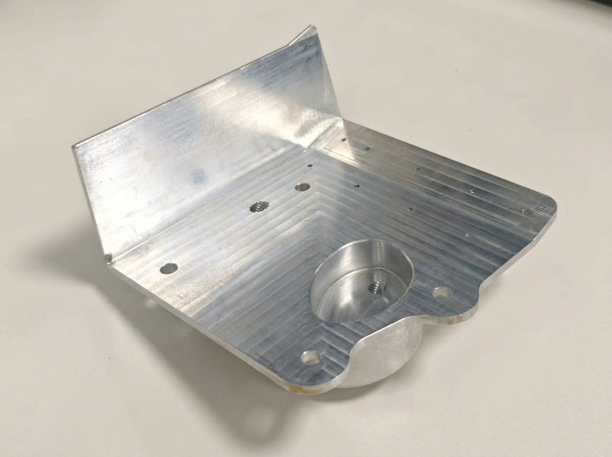
• A bent, flanged leg rather than a cast rib — on the machined prototype this geometry is milled or formed from plate; on the production casting, it will likely be part of the same single pour.
• Blue witness marks and scribe lines — typical residue from a coordinate measuring machine (CMM) inspection or first-article layout check, confirming the part was built for dimensional validation, not final assembly.
Why Build the First Units in CNC-Machined Aluminum Instead of Casting
Automotive mount brackets are almost always destined for high-volume die casting or permanent mold casting once a program reaches production — casting is simply cheaper per unit at scale. But nobody cuts casting tooling, which can take eight to twelve weeks and cost tens of thousands of dollars, based on a CAD model alone. CNC machining fills the gap for a few concrete reasons:
• No tooling lead time: a machined bracket can be cut from bar or plate stock in days, so engineering teams can test fit and function while the casting die is still being designed.
• Design changes stay cheap: revising a CNC program costs a fraction of revising a casting die, so late-stage geometry changes — a moved bolt hole, a thicker boss wall — don't blow up the program schedule.
• Material can be swapped for testing: this is where 6061-T6 CNC prototypes and A356-T6 cast production parts typically diverge — 6061-T6 wrought aluminum machines cleanly and offers higher tensile strength for the same wall thickness, while A356-T6 is chosen for the final casting because of its castability and pressure-tightness in complex, thin-wall geometry, a trade-off covered in more detail by material suppliers comparing the two alloys.
• Bridge production covers real test builds: a similar approach is documented in a published case where a supplier CNC-machined an A356-T6 engine accessory mounting bracket to ±0.005" tolerances for vehicle build validation ahead of full production tooling.
What Machining a Two-Boss Mount Bracket Actually Involves
1. Stock and fixture planning: the blank is typically 6061-T6 plate or billet, fixtured to hold the base flat while both bosses and the bent leg are accessed without repositioning error stacking up.
2. Roughing: bulk material is removed around the boss features and pocket pattern first, leaving stock for finishing passes so heat and cutting forces don't distort the thin flanged sections.
3. Boring and spot-facing the bushing bores: this is the most dimensionally critical step — bore diameter, roundness, and depth control how well the isolator bushing presses in and how it performs under vibration load.
4. Pocket and rib milling: the triangular lightening pattern is cut to match the target weight and stiffness of the eventual casting, letting engineers validate the structural concept before it's locked into a die.
5. Forming or machining the flange leg: depending on the design, this bent section is either pre-formed and then machined, or cut from solid on a multi-axis mill to hold the same angle the casting will eventually produce.
6. Deburring and edge break: all bore edges and pocket walls are deburred, since sharp edges on a bushing bore can damage the rubber isolator during installation.
7. First-article inspection: critical bore and flange dimensions are checked on a CMM against the drawing, with layout marks left on the part as a record — exactly what shows up as the blue scribing in these photos.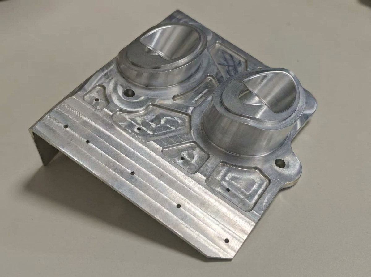
Precision Requirements That Actually Matter for a Motor Mount
A mount bracket is a load path and a vibration isolator at the same time, so tolerancing isn't just cosmetic. Bore concentricity and roundness govern how evenly the isolator bushing loads under torque; flange flatness governs whether the bracket seats without pre-load against the engine or chassis face; and bolt hole position tolerance determines whether the part bolts up without binding across an assembly line. Automotive-sourced parts, in particular, tend to move through supplier quality processes, which is why first-article inspection and dimensional traceability — not just a good surface finish — are part of a serious automotive bracket program from the prototype stage onward.
Finishing: Corrosion Protection Matters as Much as Geometry
A bare-machined aluminum bracket like the one in these photos won't leave a shop floor looking that way in production. Once geometry is validated, most automotive mount brackets go through a corrosion-protection step before they ever see an underhood or underbody environment, since aluminum will still pit and stain under prolonged exposure to road salt and coolant splash even though it doesn't rust the way steel does.
• Chromate or trivalent conversion coating: a thin chemical layer applied before paint or e-coat, mainly to improve paint adhesion and add a first layer of corrosion resistance.
• Anodizing: builds a harder, more wear-resistant oxide layer directly on the aluminum surface, often used where the bracket stays unpainted or where dielectric properties matter.
• E-coat (electrophoretic coating): the same process used on vehicle body panels, applied when a bracket needs full coverage into bores and pockets that spray painting can't reach evenly.
MK Machinery runs conversion coating, anodizing, and related finishing in-house through our surface treatment service, so a bracket program doesn't need a separate finishing vendor once machining is complete.
Bridge Production: Real Parts While Tooling Is Still Being Built
This machining approach is often called bridge production — producing functional, near-final-geometry parts in CNC-machined metal to bridge the gap between prototype and tooled production. MK Machinery runs this exact workflow for automotive and electronics clients through our rapid prototyping and small-batch trial production capability, then transitions the same design into volume manufacturing through our in-house precision casting service once the geometry is validated, so the part doesn't have to change manufacturing partners mid-program.
Sourcing Support for Automotive Bracket Programs
We've supported similar automotive component work at production volume, including our automotive engine block processing case, and cover the broader question of choosing a manufacturing partner in our guide to CNC machining suppliers in China. The same core capability — tight-tolerance CNC machining backed by real quality control — applies whether the part is a one-off validation bracket or a running production order.
Need a Reliable Partner for Your Next Automotive Machining Program?
If your team is validating a mount, bracket, or housing design ahead of tooling, MK Machinery can machine functional aluminum prototypes and bridge-production batches to the same tolerances your final casting will need to hit. Our shop runs multi-axis CNC machining, in-house precision casting, and CMM-based first-article inspection under one roof, so your part doesn't lose fidelity moving from validation to volume production. We work with automotive engineering teams on everything from single validation units to full production runs, with documentation and dimensional reports ready for your own quality process. Send us your drawing or STEP file and we'll scope material, tolerance, and lead time.
Get a quote: mk-cnc.com/contact | Explore our CNC machining capabilities: mk-cnc.com/services/cnc